ANALOG BENCH ATE
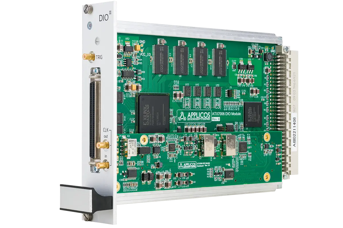
APPLICOS DIO-II Module
A multimode digital source and capture module
The module combines very low jitter clock generation at high data rates.
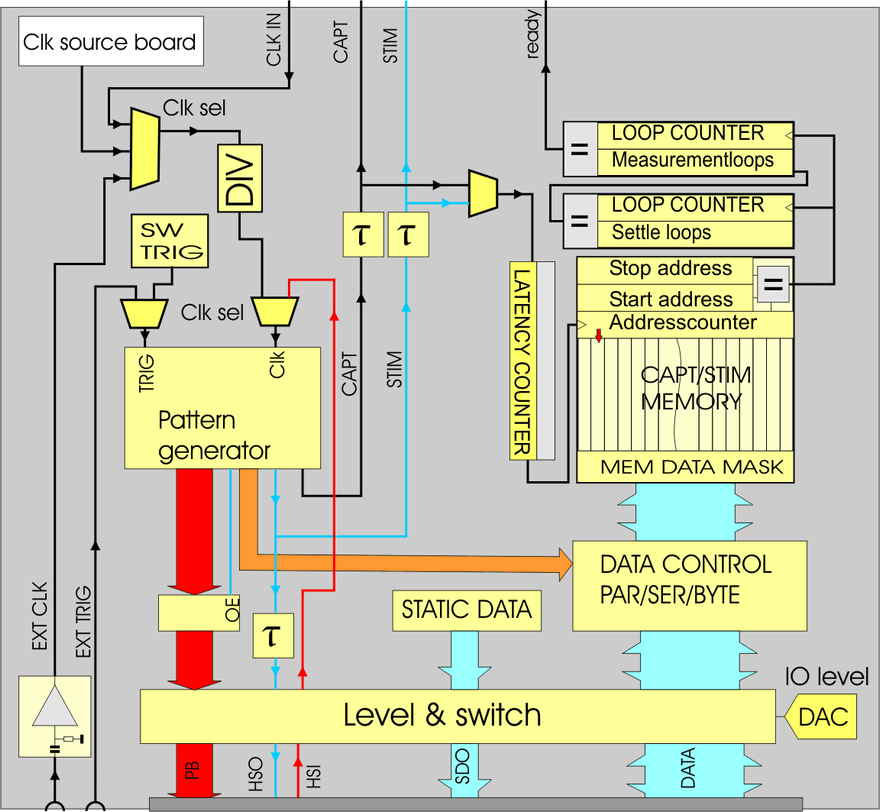
In Low Speed Mode it provides a 20-bit parallel or 24-bit serial I/O capability running at speeds up to 50 MHz. In High Speed Mode, the DIO-II provides a 16-bit parallel I/O capability up to 200 MHz. In both Modes, the Clock is generated by a low jitter PLL source that is capable of generating clocks from 320 kHz up to 1 GHz. In low speed mode the maximum usable clock frequency is 100 MHz, in High Speed mode the maximum clock frequency via the backplane is 600 MHz and via the front clock 1 GHz.
The DIO-II supports external clocking (in or out), external trigger and frequency synchronization with an external reference source.
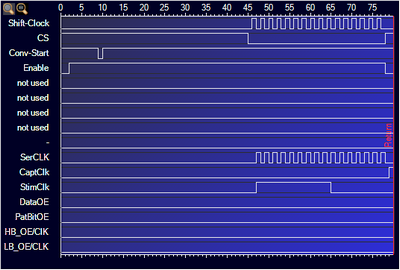
The DIO-II offers 8 Pattern Bits to the user for DUT synchronization and control. The remaining 8 Pattern Bits are used for control and synchronization of the analog source and capture modules through the ATX backplane. The flexible pattern bit structure enables the implementation of various serial protocols as SPI, I2C, I2S, etc. This ensures coherent mixed-signal measurements thereby improving the accuracy of your measurement without need for "post-process" windowing.


| General | |
|---|---|
| Clock jitter (typical @ 100 MHz) | 190 fs |
| Independent delay per clock | 0-32 ns (~0.5 ns resolution) |
| Trigger input threshold level | 1 V (1 kΩ) |
| Pattern bit trigger capability | DC - 5 MHz |
| Front panel clocks | |
|---|---|
| Clock output level (typical) | 1.5 Vpp / 50 Ω |
| Clock output frequency | 320 kHz - 1 GHz |
| Clock input Low Speed mode | DC - 100 MHz |
| Clock input High Speed mode | 1 MHz - 400 MHz (ref. clock in) |
| Clock input threshold / imp. | 0 V or 1 V (programmable) / 50 Ω |
| Low speed mode | |
|---|---|
| Pattern Generator | 100 MHz, 128kwords x 16-bits |
| Data I/O Pins | 20-bit parallel / 24-bit serial |
| Data I/O Formats | parallel, byte-by-byte, serial |
| Source/Capture Depth | 4M-words x 24-bits/8M-words x 16 bits |
| Internal clock frequency | 320 kHz to 100 MHz |
| External clock frequency | DC to 100 MHz |
| Data source/capture rate | DC to 50 MHz |
| I/O Levels | VIL: 0.4 V (max), VIH: 1.2 V, 1.8 - 3.3 V |
| High speed mode | |
|---|---|
| Data I/O Pins | 16-bit |
| Data I/O Formats | parallel |
| Source/Capture Depth | 8M-words x 16-bits |
| Backplane clock frequency | 320 Hz to 600 MHz |
| Data source/capture rate | DC to 200 MHz |
| I/O Levels | LVDS |
Separate Stimulus clock, Capture clock and DUT clock. All derived from the same low jitter main clock
